
Introduction #
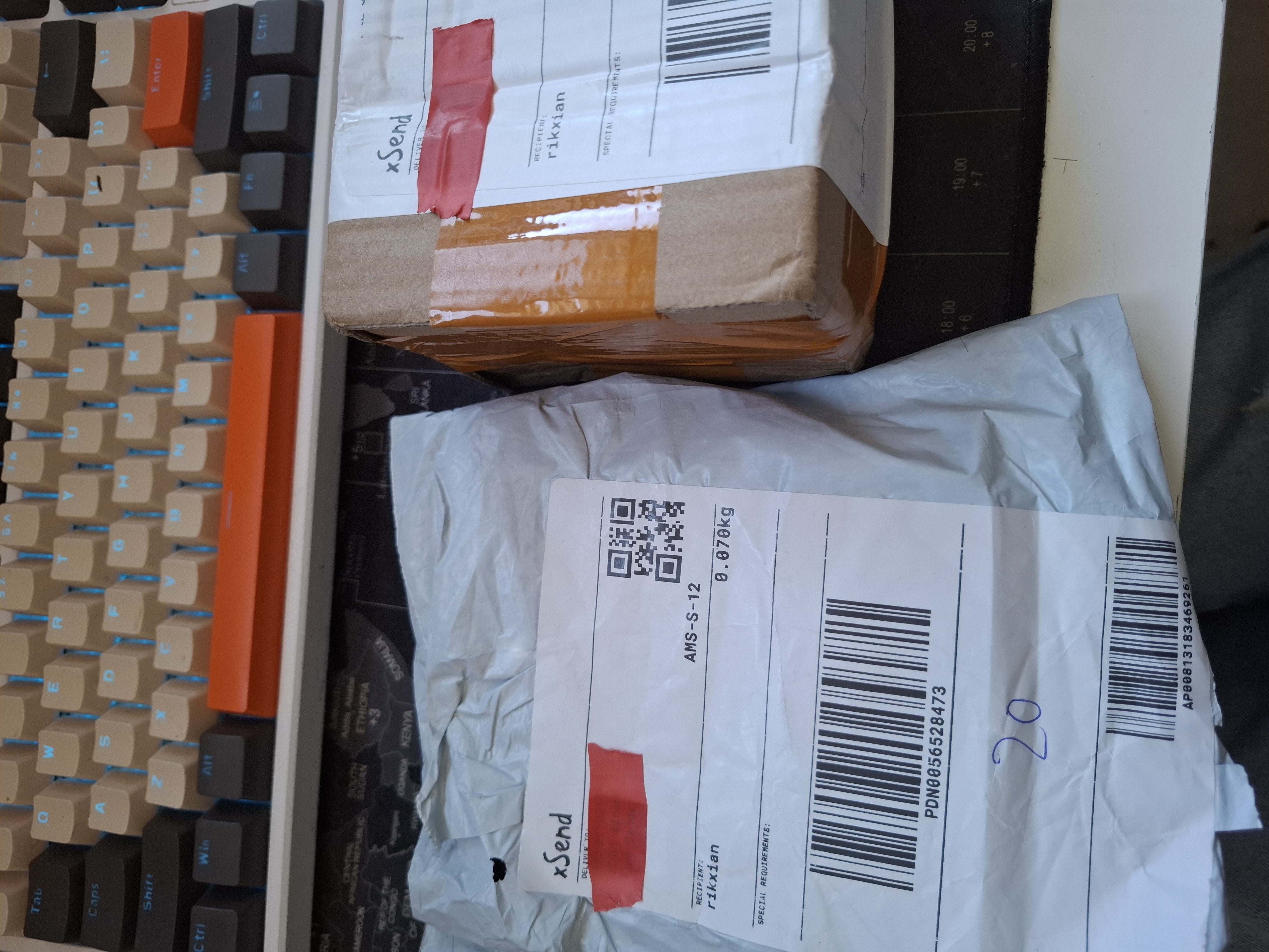
So finally the radxa cm3 and carrierboard came in! Also i ordered a bunch of other stuff that you will see in the photos down below but that are not of any relevance related to the MusicBox project.
Items
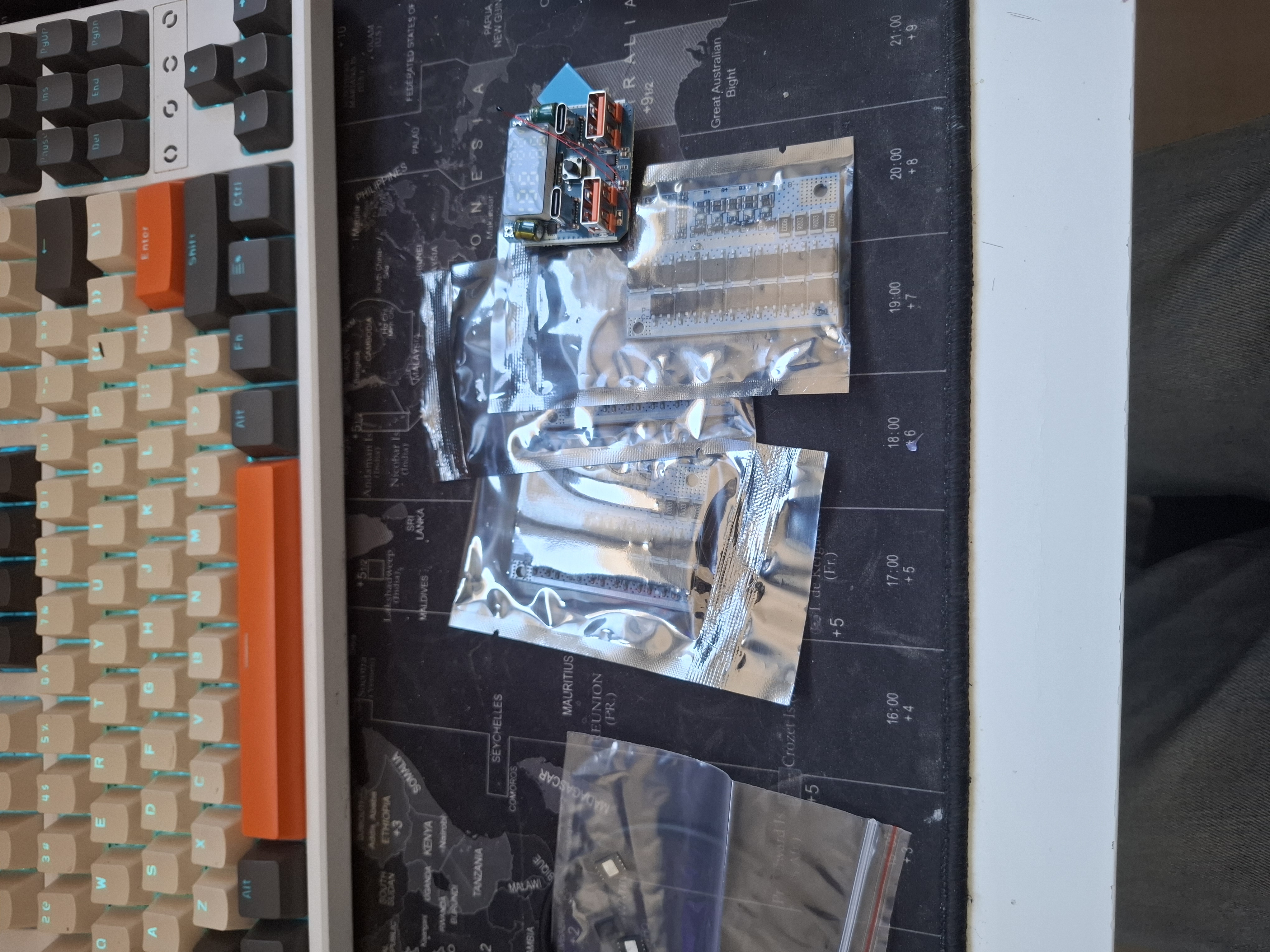
First the other items i also ordered. These are for making a 100w powerbank and are not relevant to this project. As you can see i ordered some BMS (battery manage system) boards and a powerbank board which supports usb c pd up to 100w and i also ordered a heatsink as i know that 100w will create some heat on the main ic chip on the back.
A bit more unpacking of the box which has the interesting stuff.
And here we got the radxa cm3 module and its carrier board
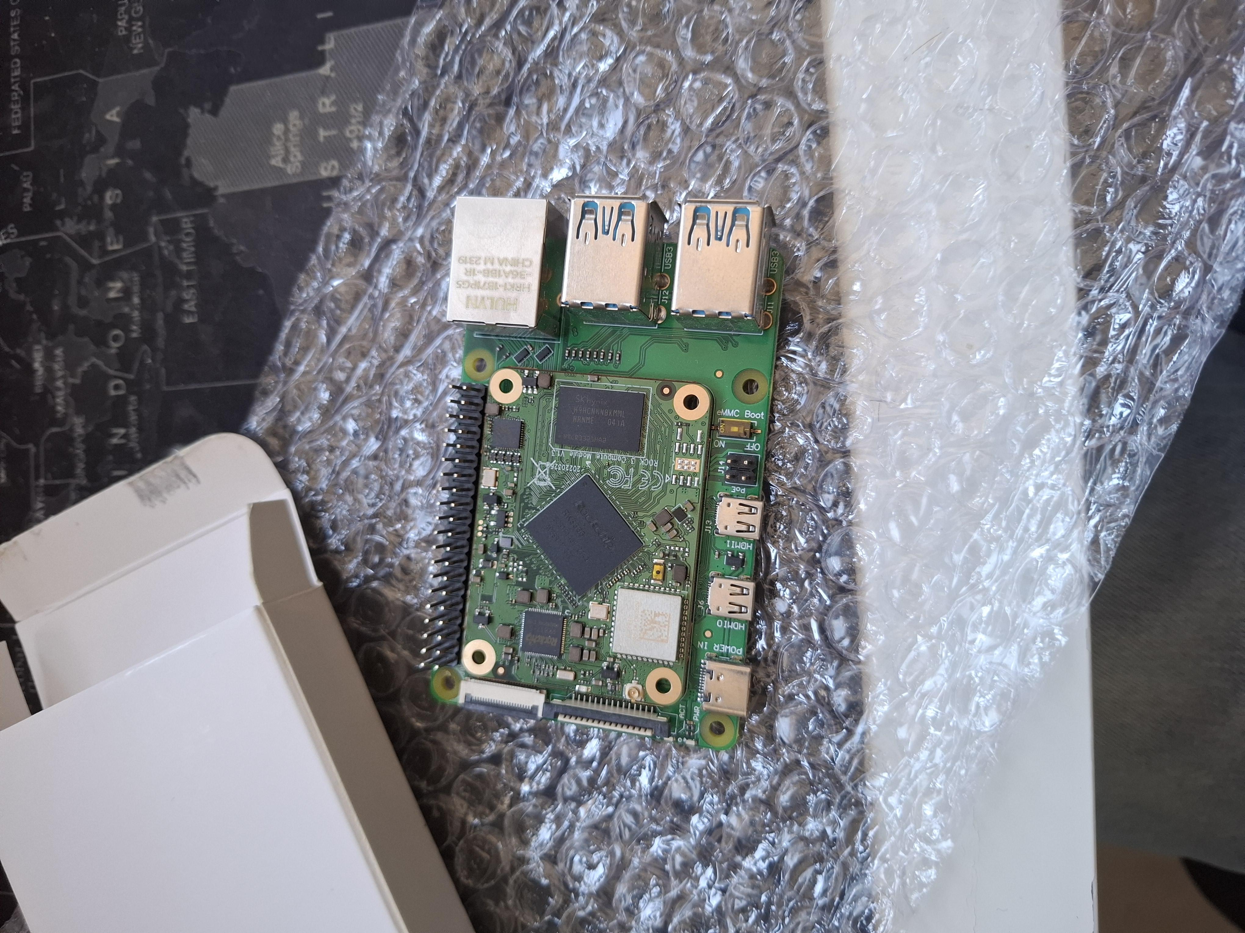
The board itself. #
So as you can see from above pictures it looks like a raspberry PI. In reality it is a carrierboard in the form and layout of one but instead of a cpu, dram and flash/emmc soldered directly to the board, it has a little daughterboard module that holds those so you can swap that out with any module compatible with raspberry pi’s CM4 module. And you can see that in the downright on the cm3 module is an empty spot for a spi flash chip and a button that will disable that spi chip so you can put it in bootrom mode. a similar populated button is that yellowish component near the wifi module and its to disable the EMMC. And it causes the same effect of the board going in bootrom mode.
Some trouble and maybe i was too quick. #
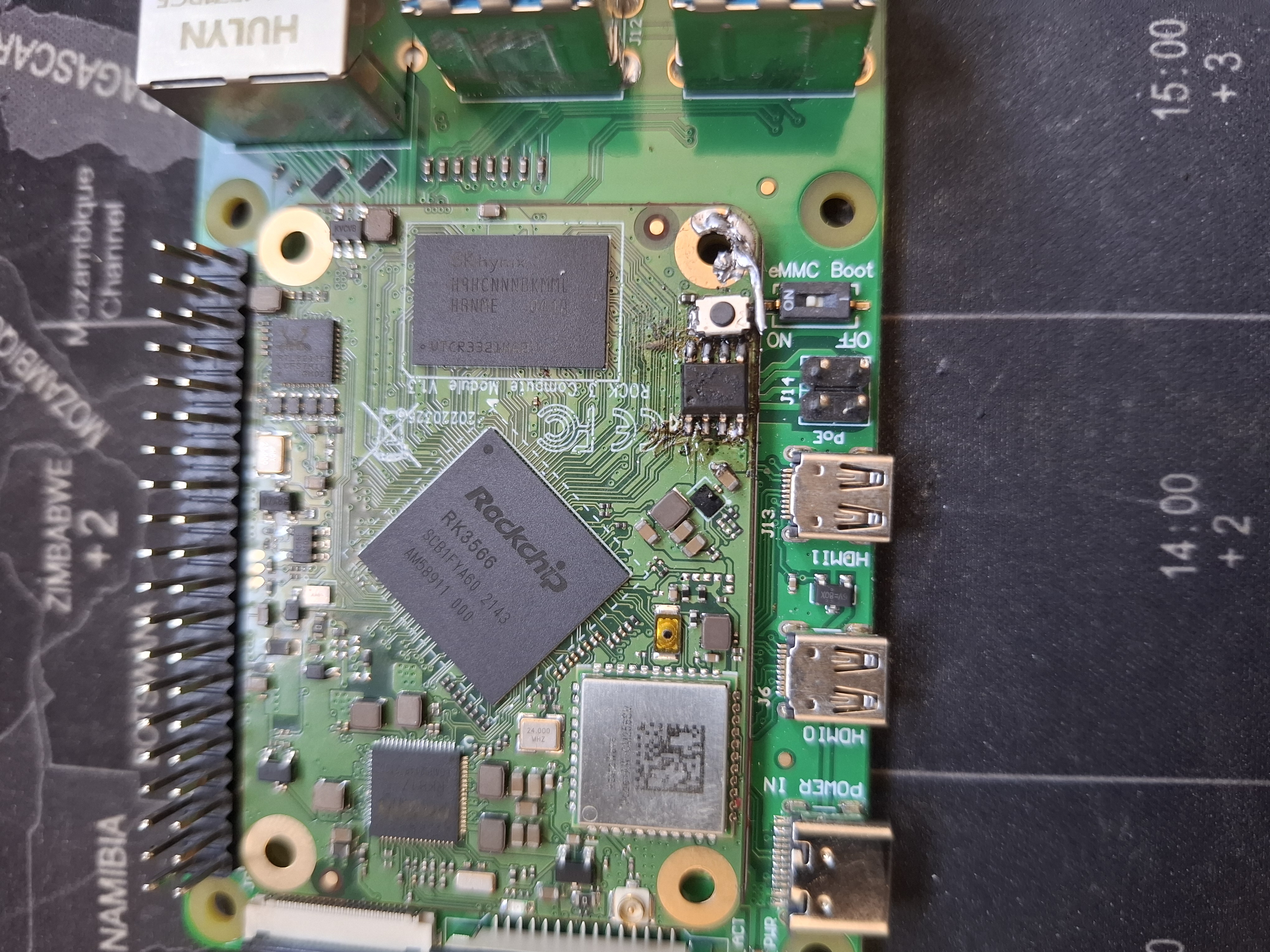
SO i decided to immideatly solder in an SPI flash chip. But i had one problem, it aint going to fit as the footprint is much smaller. I later read its a USON/WSON package format which is smaller in size. So i dug around and found an old ESP module that did have a flash that would fit so i soldered it on. But due to my stupid mistake of not first doing proper research on what flash chip to fit i did buy the wrong ones form aliexpress which where a lot larger. Thats not a problem in itself but then i noticed that the board would not detect the flash chip of the esp i soldered on. Later research and a bit of measuring with a multimeter showed that it was only fed 1.8v so that means it obviously wont accept/recognise a 3.3v flash chip as thta needs 3.3v and might even use 3.3v logic signals… I never seen this before but yeah no flash chip i had worked as all of them where 3.3v chips and a lot of them where physically larger. Below you can see my horrible soldering attempt and because the flash is not compatible the rkdeveloptool would not detect it…. Whoops thats a pain in the arse really! So now i ordered some gd25lq128 chips from aliexpress from a reputable seller. I know these are definitely 1.8v. But now i kind of hope the PCB quality is good as i dont want to rip off any pad as this little board and carrierboard has costed me already 80 euro which is not cheap… Also i burned some of my flux so probably my iron was too hot. SO yeah sadly i have to wait another 1-2 weeks for the new flash chips to come in and then i hope that i can save it and not rip off any solderpads/traces as its also a multi layer pcb so patching aint gonna work.
End/conclusion #
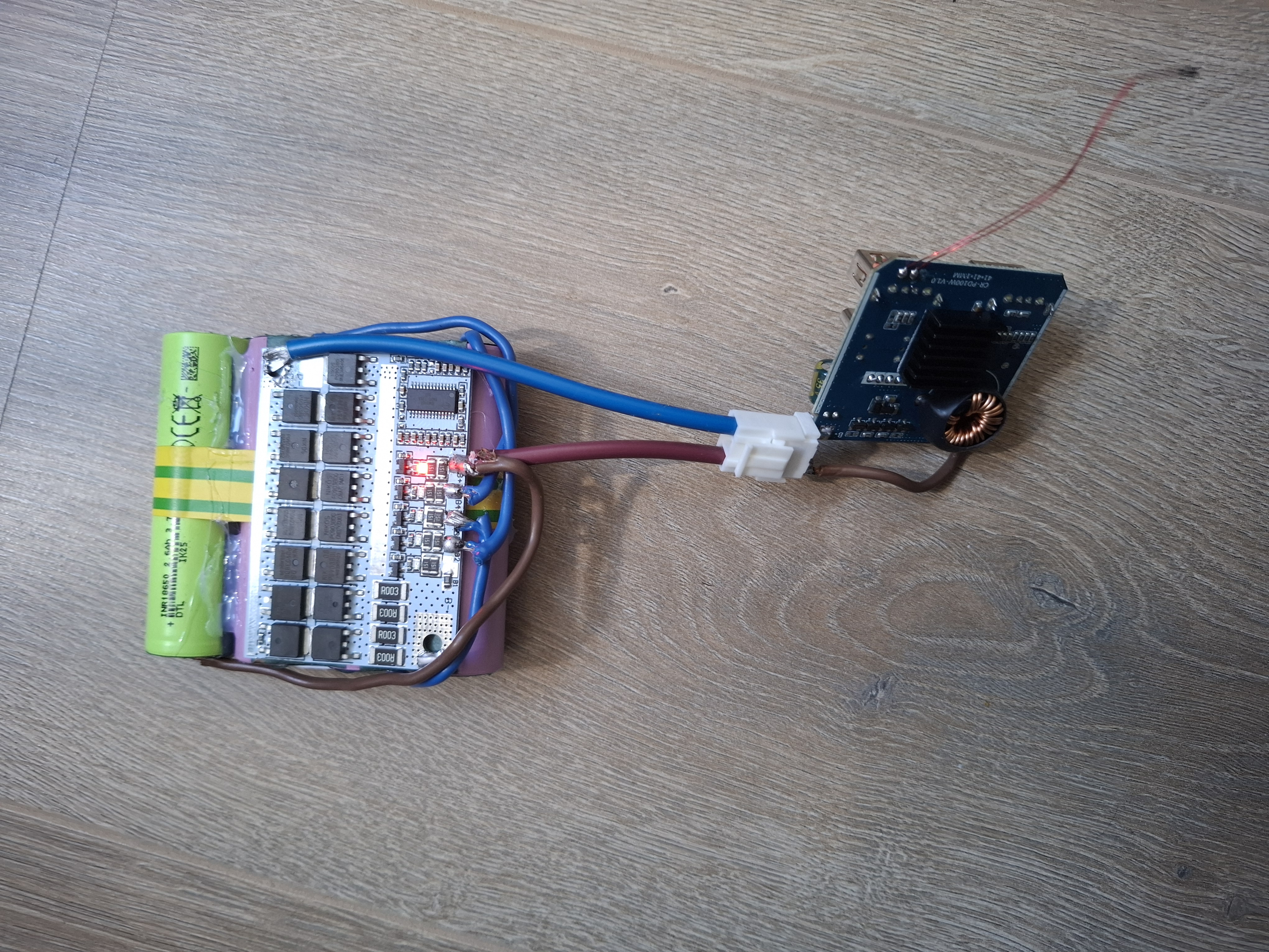
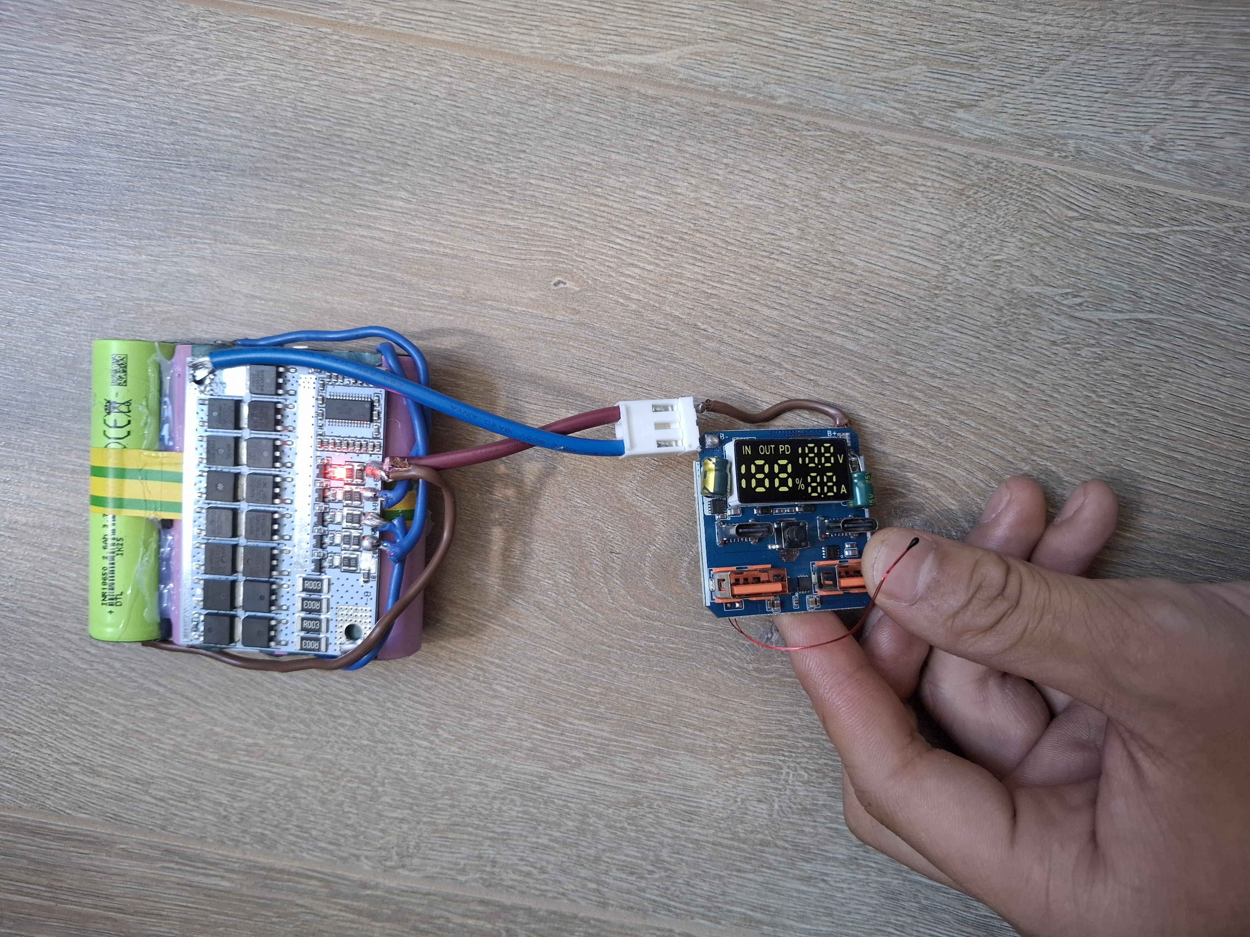
So yeah dont hurry up as that can create mistakes or situations that are in the future a pain in the arse to fix. I was too excited but maybe i was too fast. Also i might have hurried as at the end of the day we will go to a company hosted party where my nephew is (co)founder off and we also plan to sleep there too so i do not have time in the evening. Atleast i managed to build the powerbank and its battery pack. it consists of some old 18650 cells i got from laptop batteries. Because the powerbank module needed a 4s (4 cell) balanced battery pack, i needed to hook it up to a 4s BMS that will protect the batteries against overcharge, overdischarge, short circuit, overheating as lithium batteries can provide a ton of power and you dont want that to escape as heat or possibly a fire, so you need to take really good care of them. But the pack works and it has not yet exploded or caught fire. I did use extra thick proper guage wire to be able to handle the 100w (20v at 5A).
Welp, thats it for now. Now i have to wait again for another post about this project but hope its worth it. Sadly i do have school next week so i dont know how much time i have to spend on my hobbies.
I do have to test it under serious load yet but that will come another day. And i need to find or create a box for it to put it in as otherwise it would look quite sketchy and ugly. The wires are from an old extension cord so realy thick wires. I bought a set of 3 different bmsses and i did not really know which was the 3s/4s/5s variant but after some digging around i hopefuly found a picture of the good one. Thye look similar but there is 1 0 ohm resistor which basically “programs in” a setting in the BMS control ic and on the 3s and 5s variant that has different spots that it connects or its omited completely.
Also its quite hot today in the Netherlands (around max 23-24 degrees and suny) so the rest of the day i simply relaxed a bit. And in this morning i went to get my hair cut at our barber and for the rest of the day it was pretty chill.